Cordova
|
Creator: |
Contents
Overview
Cordova is the current code name for a two person quadrotorcraft with an estimated lifting capacity of 500lbs. This should be enough power for two people plus some stuff. There will be four rotors, one on each corner of the craft. The seats will be back to back so the two passengers can see everything around them. The rotors will be powered by electric motors, but there will be a diesel generator to provide power to the motors and a backup battery for emergency landings and to maintain flight control in the event of power loss. The choice of diesel is mostly because of energy density when compared to batteries. We don't plan to fly this very high.
Flight Equations
Motors: The cross shape is aligned along the pitch and roll axes. Motors are M1 through M4 with M1 at the front of the aircraft and M2, M3, and M4 arranged clockwise from the front. M1 and M3 spin clockwise while M2 and M4 spin counter clockwise.
Controls consist of a joystick comprising the X and Y input variables. A throttle comprises the Z input variable. A left/right joystick component comprises the yaw input component W. W, X, and Y need modification on input to scale from 0-255 to -128-127.
M1 = Z - W + Y - X
M2 = Z + W + Y + X
M3 = Z - W - Y + X
M4 = Z + W - Y - X
Proof of Concept
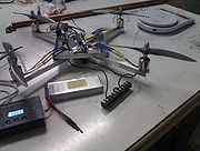
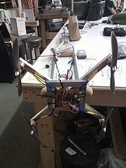
The PoC will be created using standard model aircraft speed controllers, motors, and propellers. It will be battery powered and have a IMU for stabilization.
Tasks
- Get sixaxis/laptop interface solidified
- Verify autostabilization code
- Read from the IMU faster using multibyte reads if possible
History
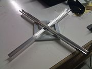
- 21 Aug 2010 - Cut and assembled frame with rivets
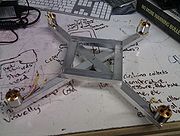
- 30 Aug 2010 - Mounted first motor
- 1 Sept 2010 - Mounted remaining 3 motors and soldered first speed controller
- 7 Sept 2010 - Soldered remaining 3 speed controllers
- 10 Sept 2010 - Spun up first motor, speed controllers work exactly like servos, 50Hz, etc.
- 11 Sept 2010 - Mounted new motors to frame
- 13 Sept 2010
- Shrink wrapped 2 speed controllers for electrical safety
- Created a power bus to hook up multiple motors
- Ran 2 motors simultaneously with a bit of vibration
- It has become obvious that I need better blades that are already balanced and the correct size (instead of milling them out)
- 14 Sept 2010
- Got and tested new 9x6 blades. These should provide more thrust than the 8x4.5 blades and be more durable and balanced.
- Shrink wrapped the remaining speed controller connections.
- Still need 3 loop connectors to connect the speed controllers to power. Getting these tomorrow.
- 15 Sept 2010
- Fixed grounding issues causing pwm to go wonky
- added connectors
- drew blood (thanks ethan, now it has a taste for human flesh)
- produced enough lift to more than compensate for onboard electronics and batteries
- current weight is 2.6lbs including all batteries and electronics
- one motor obviously has more friction than the others causing it to run slower (this needs to be taken care of)
- 16 Sept 2010 - ordered new motor to replace high friction motor
- 17/18 Sept 2010 - figured out how to initialize speed controllers properly
- 20 Sept 2010
- got the new motor in and installed it
- cleaned up the motor mounts so the screws go in cleaner
- ordered the remaining parts required for the control system
- discovered that one of my pull props has a chip out of it from when it tried to eat the table
- 23 Sept 2010 - Received sparkfun order with xbee adapters, IMU, and UART/SPI/I2C converter chip
- 24 Sept 2010
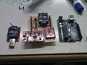
- Received protoboard and long headers from adafruit
- Rebuilt the PWM interface on the protoshield and added power capability
- Placed components in preparation for female header interface
- Soldered male headers to xbee, serial converter chip, and IMU
- 25 Sept 2010 - Soldered down female headers and wired power to all chips
- 26 Sept 2010
- Set I2C address to 0xA4 for the UART chip and wired the I2C/UART header to the IMU header
- Started writing I2C convenience functions for reading and writing bytes
- 27/28 Sept 2010
- Did minor soldering where required, finished up I2C/UART interface code
- The I2C lines need pullup resistors (4.7K)
- 29 Sept 2010 - Connected I2C lines to pullups, still no response from the chip
- 30 Sept 2010 - Got a replacement propeller for the one that is chipped
- 1 Oct 2010 - Got the replacement motor
- 2 Oct 2010 - Got the I2C interface working
- I2C interface code was correct
- A0 and A1 address selectors were not being set correctly (moved them to Vdd for address 0x90)
- The reset line was incorrectly set
- 6 Oct 2010 - After a few days of struggling, the IMU now has new firmware on it from the AHRS project
- 11 Oct 2010
- Work on this has paused for the past couple days
- The IMU is now talking through the I2C/UART and passing data correctly!
- A few registers were not being set correctly (xon/xoff and 8n1)
- The xbee link is now working at 9600 baud (this needs to be bumped up to 57600)
- 16 Oct 2010 - Got most of the PD control code written
- 18 Oct 2010
- Had to fix minor connection problems and remount one of the motor controllers
- Got the drone operating independently (no flight yet)
- 20 Oct 2010 - Figured out the issue with the PWM output (bad crimped pin)
- 21 Oct 2010
- Fixed type overrun problems causing erratic behavior in reference error calculations
- Corrected signs on pitch and roll inputs
- Need to eat the first several seconds of readings to let yaw stabilize to magnetic north
- 25 Oct 2010
- Fixed bug where the initial state was not being set, so all references were absolute
- The yaw state drifts for 260 or so samples to align with magnetic north when first powered on
- Code now in svn
- 26 Oct 2010 - worked on control code, pitch and roll only
- 27 Oct 2010
- Went to test and discovered that both my batteries were toast
- Battery A had a propeller impact site (antimov, anyone?)
- Battery B was drained well below tolerances for LiPo cells
- The speed controllers were set to avoid this situation (cheap PoS speed controllers)
- There is a possibility of recovery for this battery, but I will never trust it again
- I need 2 new batteries...another $60
- 1 Nov 2010
- Undamaged battery is unrecoverable
- New batteries have been acquired with higher capacity, but less output capability
- Prototype is now mounted to a pole for more testing
Parts Required
- 2 matched blade pairs
- 9"x6 blades from RC hobby barn, $4.96 each (Purchased)
- 4 rc airplane motors
- 950RPM/V, 200W, 18A (max), 10x7 capable motor from RC hobby barn, $20.82 each (Purchased)
- 4 rc airplane speed controllers
- 40A speed controller $16.00 ($64.00) (Purchased)
- Channel aluminum
- 2x11.1V 3AH LiPo battery from RC hobby barn $29.99 ($60) (Purchased)
- LiPo battery charger from RC hobby barn $35 (Purchased)
- atmel/arduino for motor control ~$30 (Purchased)
- User input
- PS3 bluetooth controller
- Telemetry and control
- Xbee $42.95 ($85.90)
- 6mi range
- 50mW
- 900MHz
- Need 2 modules (one for each side)
- usb interface adapter $24.95 (Purchased)
- arduino shield adapter $24.95 (Purchased)
- Xbee $42.95 ($85.90)
- AHRS: 9DoF with 3DoF Gyro, Accelerometer, and Compass
- Razor IMU $124.95 (Purchased)
Stage 1 - Basic Flight
exclusively remote control, direct control input, mixing of controls based on equations above in the microprocessor
Stage 2 - Assisted Manual Flight
Add the IMU to the system.
The atmel will take in raw input channels and mix them according to the equations above like before, but will correct pitch, roll, and overall thrust based on gyro data.
Stage 3 - Automated Stabilization, Hover, and Movement
Add a GPS to the system for location. Real time control via simple instructions.
Instructions:
- Move X meters <direction>
- where direction is one of: up, down, north, south, east, west, (north|south)-(east|west)
- Move to <DD or DMS latitude>,<DD or DMS longitude>[,<altitude in meters>]
Loss of signal results in unit moving back to the location where it powered on unless explicitly told not to.
