Multitouch screen
Contents
Overview
A touchscreen interface that allows for multiple points of contact for uniquely manipulating objects and information on screen.
Status
Built, working on the software from here on out.
Design concepts
- Ideally would be linked to screen resolution rather than physical size making it highly scalable.
- A transparent layer capable of being laid over any existing screen, projected or otherwise.
- System software would control generic interaction techniques that would work with all existing applications as well as newly developed ones.
Existing designs
- Jeff Han's: Acrylic sheet backed with a difuser(a solid surface to project on) and lined along the side with LEDs in a mobile frame capable of holding the projector and camera below the screen. A small solid lip surrounds the edge of the acrylic to prevent the light from escaping at acute angles causing the light to be reflected internally along the full length of the sheet. Placing a finger or other object on the surface causes light to scatter in a mostly perpendicular direction to the sheet making a bright spot on the difuser below which the camera then picks up and registers as a manipulation point. It is unknown that type LEDs Jeff Han uses, but other examples use infrared LEDs, which most digital cameras/webcams are capable of picking up. This is likely the cheapest way to produce large multitouch screens.
Preliminary notes
Working off the Jeff Han design, that is to say acrylic sheet with IR LEDs, projector from underneath, and IR sensitive camera, I'm going to see how shallow I can get the table by use of a concave mirror. The concave mirror should make the image larger, thereby decreasing the distance the projector needs to be from the projection surface, but will flip this image(easily corrected on the projector itself).
Progress
- 05/13/2007: Obtained a dinner plate sized convex mirror. Testing on focal length distance and size increase can begin.
- This type of mirror doesn't look like it's going to work out. Too much distortion around the edges. --strages 06:34, 31 May 2007 (CDT)
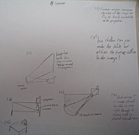
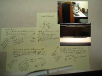
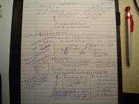
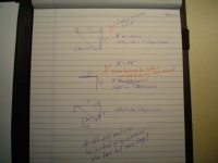
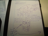
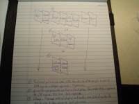
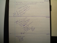
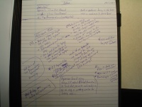
- 05/31/2007: Given the release of Microsoft's Surface it got me thinking. I can make a better multitouch surface....with blackjack and hookers. Haven't quite figured out how I'm going to do the hookers part just yet, but managed to come up with a reasonable enough blackjack solution(see notes above). Came up with an alternated design based on the desks we have at work after a discussion with a coworker trying to explain the flexibility of having a large multitouch surface(again see notes above). Also came up with an idea for doscument "scanning" based on what Nykodemus has been doing with his book "scanning" rig, which strangely isn't on the wiki(ahem!).
- I'll be needing a basic physics engine, preferably one that runs on top of all the applications as opposed to a per application basis, that handles "throwing" of windows and basic collision between windows.
- 09/28/2007: Purchased a 32"x48" piece of lexan for $50. It should have the same properties as acrylic, not that it matters because I've decided to use the Diffused(shotgun) illumination method.
- 09/29/2007: The guys and I several tests with the lexan and a projector to determine optimal throw distance and all. Given the information we learn we panned out a design for the table that allows for it to tilt from flat to vertical without the need for recalibrating the setup.
- 09/30/2007: Purchased all the wood needed to build the frame for the table. Ran into some snags with cutting it all, but progress was made. There still needs to be an IR illuminator and mirror purchased.
- 10/02/2007: Went in search of IR LEDs at Mock Electronics, but they had none and recommended I go to W&W Electronic. It was too late to go there today. I went to the.narro.ws to get some help on making the table run on Linux, but it turned out the camera wouldn't support the resolution we needed it to in Linux to work well, so we're stuck using Windows.
- 10/03/2007: Went by W&W Electronics but alas they has no IR LEDs either. Later on I met up with Korc at his place and worked on the table some more. We got the frame cut that goes around the Lexan and realized we had to redesign the base as it was just going to be too low to be usable in a vertical mode. We opted to go with a 45 degree tilt "vertical" mode as a compromise. Tested the projector with a mirror to make sure it was going to do as expected, thankfully that worked out. Still need to purchase a mirror and IR Illuminator, but at least I got the software and camera working like we need.
- 10/04/2007: Managed to get the frame for the Lexan cut, sanded, and glued together. Did some tests on the amount of IR that comes from an incandescent bulb and determined it wasn't enough. Ordered 100 IR LEDs from Digikey.
- 10/05/2007: Korc finished building the table and tested out angles for the projector and mirror. Didn't have everything done in time for the meeting but we did show off the build pictures and a couple of videos we took messing with the software. Everyone seemed impressed with the progress we made.
- 10/06/2007: Bought a larger mirror for $10, got another webcam to try out and see if we can get it working in Linux, and put together a simple test circuit with 24 IR LEDs which seemed to work really well. We figured out that the plastic protective film on the Lexan was just too reflective and we'll have to go with something like tracing paper or something.
- 10/07/2007: Korc built the rest of the IR illuminators and all that remains is building the cross supports for the screen to prevent side to side movement, place the IR illuminators around under the screen, find a decent reflective surface that lets IR through, frame the mirror properly, and make a new mount for the projector.
- 10/11/2007: Strages came over to work on the table---we considered different materials to place on the surface to be the screen, but which should let IR through well enough to be reflected by fingers. We tested ripstop nylon with no success, then went to look for other materials at Hancock Fabrics. There are a number of possible materials which may work, but we decided to just use the tracing paper we already have. It works ok, just with a big seam in the middle. Also talked about the cross braces and the mounting a powering of the LEDs---the back cross brace will be at a 45 degree angle with the vertical leg, but parallel with the surface. There will be two metal strips with 12 V across them, and the LED strips will have magnets on the back allowing them to stick to the metal strips and be powered (and repositionable). --Korc 22:40, 11 October 2007 (CDT)
- 10/12/2007: I made the cross braces today and got some galvanized corner-bead (for drywall) for the powered rails. Also cut wood for the mirror frame--Korc 14:27, 14 October 2007 (CDT)
- 10/13/2007: Makeshop at korc's. Installed the cross braces, routed slot in the mirror frame and glued it together around the mirror with clear silicone sealant in the grooves for a little shock absorption. Installed the powered rails with a jack on the underside of the rail accepting power from a 12 V wall wart korc is letting strages borrow for the project. Finalized positioning for the projector.--Korc 14:27, 14 October 2007 (CDT)
- 10/16/2007: Korc and Strages got the projector and camera mounted only to realized that the placement of the IR LEDs was causing a bright band of IR in the center and very little from top to bottom. We tried diffusing the LEDs with sand paper but it only helped mildly.
- 10/17/2007: Moved the power rails to the front cross brace and attempted to scatter the light using a shield of aluminum foil but to no avail, just made more bright spots. In the end we tilted the power rail up towards the screen and placed the camera on the mirror facing up to get a better view. This worked out a lot better, but illumination was still very weak at the top.
- 10/18/2007: Korc made extensions to the power rails along the sides and redistributed the IR LED strips which drastically improved even illumination of the screen. It was decided that this was good enough and further tweaks were just going to have to be made at Phreaknic. In the end the table was disassembled but unable to fit in the car for transport due to the photobooth mark I taking up all the room. It sits currently disassembled in Korc's garage for the time being.
- 10/26/2007: Moved to the Narro.ws
- 04/22/2008: Moved to the shop
- 04/24/2008: Re-assembled the table with the help of Nykodemus and Tanstaafl.
- 04/26/2008: Nykodemus wired up the power rails, and strages got the proper filters and software working properly. After working on it a bit, looks like we either don't have enough IR or we need to enclose the base. I think it's time to do some small scale tests and work our way back up.
- 05/13/2008: Given recent work with some other multitouch tables we decided to enclose the table and forgo use of IR in lieu of shadows cast on the surface . I obtained the proper filters for the camera that invert the shadows into "bright spots" and scale up the "brightness" to make some decent blobs. Did some tests today and just about got it working. There needs to be some tweaking with the filters some more to make it work better. Work continues.
- 10/15/2008: First successful LLP(Laser Light Plane) multitouch test. Used my own laptop screen as the surface, a single 780nm laser powered off USB, webcam with IR filter removed and an IR pass filter over the lens to block out visible light. Video can be found here: http://strages.net/index.php/2008/10/15/laptop-turned-multitouch
Alternate Designs
This is a place for alternate designs by various members.
Cheap commercial design
- 17" or 19" LCD insttead of a projector.
- Saves on cost.
- User replacable.
- Flourescent lighting for backlight.
- Low IR interference.
- 1-3 Wiimotes to handle blob tracking.
- Works at acute angles.
MTmini
A cardboard box with a paper covered acrylic window on top and a webcam inside looking up at the window. Works off the shadows your fingers make on the window at the top of the box, the only light source, rendering them into blobs. Package and more information can be found here. Simple and effective.
Status
Done
Links
coffee table
19" LCD taken apart to make transparent, backlit in an alternate manner, side illuminated with IR LEDs(FTIR method), and placed in the top middle of a coffee table shaped box containing a camera sensitive to IR light with a visible light filter. This is considered to be a prototype for the cheap commercial design.
Status
Prototype built but not working yet.
Progress
- Nykodemus suggested using the IR modules from the larger non-functional multitouch table to side illuminate the coffee table. --strages 17:31, 10 June 2008 (CDT)
[22:05:56] <strages> AdmiralYOUDEE: rumor has it you've built an LCD based multitouch table [22:06:08] <AdmiralYOUDEE> that rumor is true [22:06:32] <strages> mind running through how you made yours with me? [22:06:56] <AdmiralYOUDEE> er you have specific questions? [22:07:43] <strages> I'm making one and I'm trying to do it with DI [22:07:53] <AdmiralYOUDEE> er [22:07:57] <AdmiralYOUDEE> duno how much luck you will have with that [22:08:03] <AdmiralYOUDEE> most LCDs have a layer built in to them that blocks IR from behind [22:08:34] <strages> like in the actual LCD or one of the filters once you take the screen apart? [22:08:42] <AdmiralYOUDEE> the lcd [22:08:51] <strages> :/ [22:08:53] <strages> ok [22:08:54] <AdmiralYOUDEE> at least mine and other people have reported similar things [22:09:00] <AdmiralYOUDEE> i turned all my illuminators from behind [22:09:05] <AdmiralYOUDEE> and couldnt see nethin [22:09:14] <strages> alrighty [22:10:01] <AdmiralYOUDEE> i think most people who have done LCD setups [22:10:10] <AdmiralYOUDEE> are doing a form of front illumination [22:10:16] <AdmiralYOUDEE> by lining the edges of the lcd with leds [22:10:28] <AdmiralYOUDEE> also the laser method that is being shown on the forums would work well for an lcd setup [22:10:30] <strages> yeah I was afraid of that [22:10:43] <AdmiralYOUDEE> FTIR would work as well technically, but FTIR with bare acrylic kinda sucks [22:11:40] <strages> I was hoping to do layer it, LCD->acrylic(already availble from the backlights)->camera/IR source [22:12:08] <AdmiralYOUDEE> doubt you would be able to do that unfortunately [22:12:12] <strages> to the best of my knowledge doing the FTIR method requires acrylic on top [22:12:16] <AdmiralYOUDEE> correct [22:12:25] <AdmiralYOUDEE> the ir goes down [22:12:26] <AdmiralYOUDEE> just not up [22:12:32] <AdmiralYOUDEE> its only blocked in 1 direction [22:15:38] <strages> :/ [22:16:02] <strages> I've been racking my brain trying to figure this out and for nothing [22:16:08] <AdmiralYOUDEE> you probably want to put a thin layer of acrylic on top anyway to be honest [22:16:19] <AdmiralYOUDEE> the lcd material itself isnt too robust [22:16:35] <strages> ok [22:17:25] * x29a_ (n=x29a@unaffiliated/x29a) has joined #nuigroup [22:18:01] <AdmiralYOUDEE> also theres some info on the forums [22:18:07] <AdmiralYOUDEE> about a piece of plexi that reflects light upward [22:18:17] <strages> interesting [22:18:23] <AdmiralYOUDEE> for side illuminated signage [22:18:38] <AdmiralYOUDEE> that would also work pretty well [22:20:39] * xelapond (n=alex@c-67-165-113-52.hsd1.wa.comcast.net) has joined #nuigroup [22:24:51] <strages> well thanks--strages 18:14, 22 June 2008 (CDT)
