Cordova
|
Creator: |
Contents
[hide]Overview
Cordova is the current code name for a two person quadrotorcraft with an estimated lifting capacity of 500lbs. This should be enough power for two people plus some stuff. There will be four rotors, one on each corner of the craft. The seats will be back to back so the two passengers can see everything around them. The rotors will be powered by electric motors, but there will be a diesel generator to provide power to the motors and a backup battery for emergency landings and to maintain flight control in the event of power loss. The choice of diesel is mostly because of energy density when compared to batteries. We don't plan to fly this very high.
Flight Equations
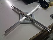
Motors: The cross shape is aligned along the pitch and roll axes. Motors are M1 through M4 with M1 at the front of the aircraft and M2, M3, and M4 arranged clockwise from the front. M1 and M3 spin clockwise while M2 and M4 spin counter clockwise.
Controls consist of a joystick comprising the X and Y input variables. A throttle comprises the Z input variable. A left/right joystick component comprises the yaw input component W. W, X, and Y need modification on input to scale from 0-255 to -128-127.
M1 = Z - W + Y
M2 = Z + W + X
M3 = Z - W - Y
M4 = Z + W - X
Proof of Concept
The PoC will be created using standard model aircraft speed controllers, motors, and propellers. It will be battery powered and have a IMU for stabilization.
Parts Required
- 2 matched blade pairs
- 8" blade pairs $4.95 ($9.90) (Purchased)
- 10" blade pairs $6.95 ($13.90) (Purchased)
- 12" blade pairs $7.95 ($15.90)
- 4 rc airplane motors
- 3800rpm/V motor $7.88 ($31.52) (Purchased)
- 4 rc airplane speed controllers
- 40A speed controller $16.00 ($64.00) (Purchased)
- Channel aluminum
- LiPo batteries
- atmel/arduino for channel mixing and motor control
- User input
- PS3 bluetooth controller
- Telemetry and control
- Xbee $42.95 ($85.90)
- 6mi range
- 50mW
- 900MHz
- Need 2 modules (one for each side)
- usb interface adapter $24.95
- arduino shield adapter $24.95
- Xbee $42.95 ($85.90)
- AHRS: 9DoF with 3DoF Gyro, Accelerometer, and Compass
- Razor IMU $124.95
Stage 1 - Basic Flight
exclusively remote control, direct control input, mixing of controls based on equations above in the microprocessor
Stage 2 - Assisted Manual Flight
Add the IMU to the system.
The atmel will take in raw input channels and mix them according to the equations above like before, but will correct pitch, roll, and overall thrust based on gyro data.
Stage 3 - Automated Stabilization, Hover, and Movement
Add a GPS to the system for location. Real time control via simple instructions.
Instructions:
- Move X meters <direction>
- where direction is one of: up, down, north, south, east, west, (north|south)-(east|west)
- Move to <DD or DMS latitude>,<DD or DMS longitude>[,<altitude in meters>]
Loss of signal results in unit moving back to the location where it powered on unless explicitly told not to.
