8x8x8 LED Cube
|
Creator: |
Overview
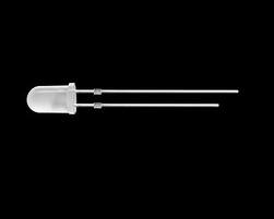
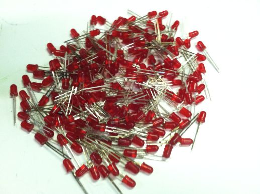
I purchased a bunch of LED's a few years ago with the intention of making LED Christmas lights with them. Here is what they look like:
I got lazy and decided I didn't want to do that project. In early May, I decided that I wanted to do something with those LED's. So I Googled LED projects and found this 8x8x8 LED Cube. I thought it was the coolest project ever so I decided I wanted to try it. Here is how I did it...
How The Cube Works
This is an 8x8x8 cube which has 512 LEDs.
An LED has two legs. One leg is called the anode, which is the positive longer leg, and the cathode, which is the negative shorter leg.
The LED cube is made up of columns and layers. The cathode legs of every LED in a layer are soldered together. All the anode legs in one column are soldered together. There are 8 layers which have 64 LED's on each layer and there are 64 columns.
Each of the 64 columns are connected to the controller board with a separate wire. Each column can be controlled individually. Each of the 8 layers also have a separate wire going to the controller board.
Each of the layers are connected to a transistor that enables the cube to turn on and off the flow of current through each layer.
By only turning on the transistor for one layer, current from the anode columns can only flow through that layer. The transistors for the other layers are off, and the image outputted on the 64 anode wires are only shown on the selected layer.
To display the next layer, simply turn off the transistor for the current layer, change the image on the 64 anode wires to the image for the next layer. Then turn on the transistor for the next layer. Rinse and repeat very very fast.
NOTE: Taken from 8x8x8 LED Cube
First Cube
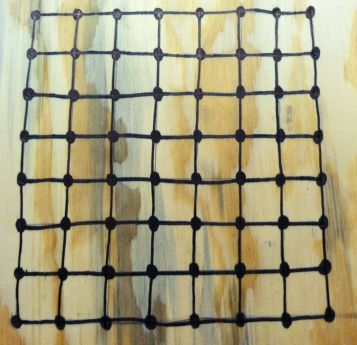
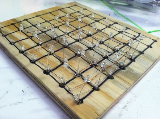
As stated in the previous section, the cathode legs of every LED are soldered together to form the layers of the cube. The easiest way to solder the LEDs together is to create a jig. Here is a pic of the first jig I created:
I knew I didn't want to use the LEDs I originally purchased for the Christmas lights because they are really flimsy. So I decided to use them to practice my soldering skills which would also allow me to figure out how the cube works. I started with a 5x5x5 cube.
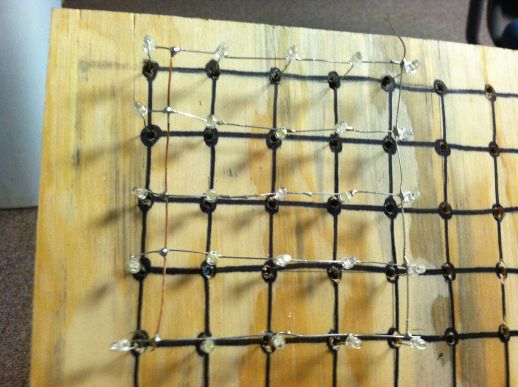
I started soldering the cathode legs together.
I then soldered a piece of wire across the cathode leg of the LEDs to add support.
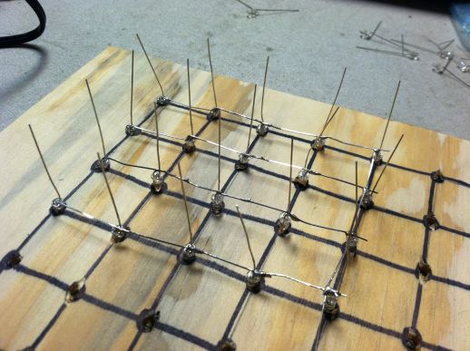
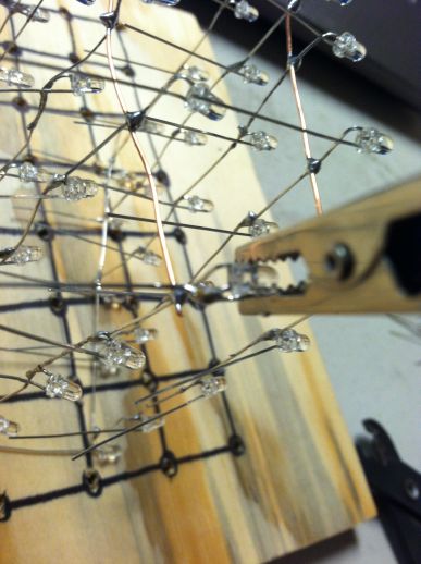
Once I got 1 layer done, I created another layer so I could figure out how to solder the anode layers together. I used an alligator clip to keep the LED leg where I wanted it.
Once I got the anode legs soldered together, I had a 5x5x2 LED Cube.
Second Cube
At this point I ran out of the White LED's. Luckily, one of our members Scott, bought out one of the electronic stores here in Huntsville...so he had so LED's to spare.
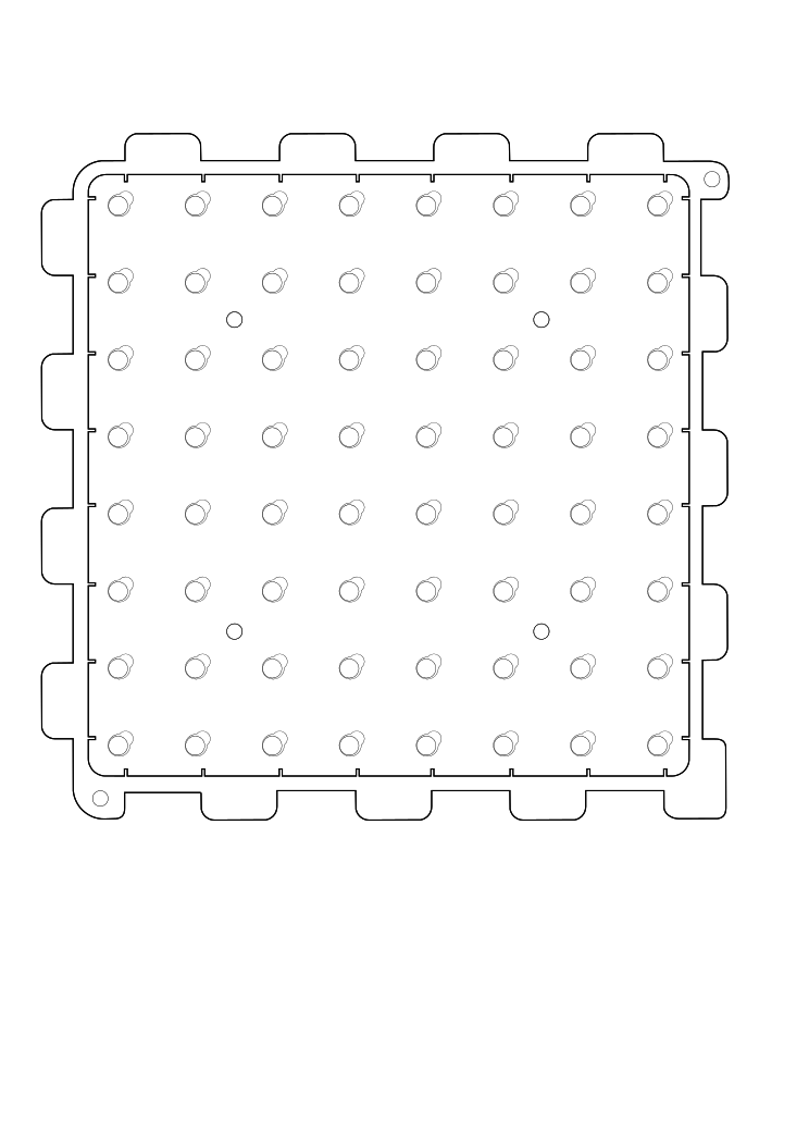
These LED's were much larger that the LED's I originally started out with. SO now that I had larger LED's, I needed a jig that could support these larger LED's. So Scott created a new jig in Inkscape. This new jig ended up added extra support to the cube. We used acrylic for the new cube and used the laser cutter to create the jig. Here is the .svg file we used to create the jig. You can right click on the .svg file to save it and create a jig for yourself if you would like to attempt this project.
Etching Driver Board
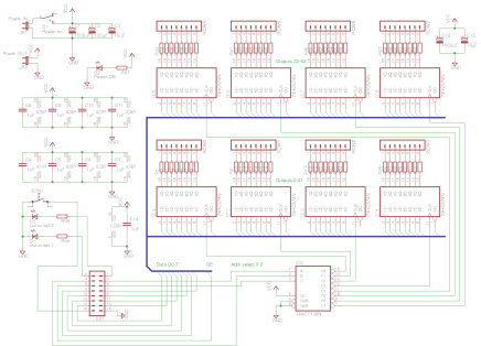
In order to control the cube, it has a driver board and a controller or power board. I started putting together the driver board first because I had all the parts I needed. I started putting the board together based off of this schematic:
I soldered the IC socket's for the 74HC574N IC's and the 74ACT138N IC on a prototype pcb board. I started making the connections for pins 1-11 of the 74HC574N IC. I thought I was supposed to solder pins 1-11 of each IC together and then solder those pins into something else. I didn't know what that something else was but I was going to figure it out later. I quickly learned I was wrong.
A bus works by connecting one pin of all 8 of the 74HC574N IC's together. So pin 1 of all the 74HC574N IC's are soldered together. All of pin number 2 of the 8 IC's are soldered together. And so on and so forth.
I asked Scott is I was wiring the board up correctly and I was quickly shot down. Scott explained to me what a bus was. I learned that it would have taking a lot of wire to accomplish creating a bus with 8 IC's. So Scott suggested we etch the driver board. This turned into a 3 day ordeal.
Here's the process of etching the board:
The first thing we had to do was look a the schematic for the driver board from the instructables site. Scott quickly realized that the schematic was created from eagle, an application to create pcb's. We copied the schematic off of the instructables site and imported it into eagle.
